- 您现在的位置:买卖IC网 > Sheet目录328 > IDT709359L7BFI (IDT, Integrated Device Technology Inc)IC SRAM 144KBIT 7NS 100FBGA
IDT709359/49L
High-Speed 8/4K x 18 Synchronous Pipelined Dual-Port Static RAM
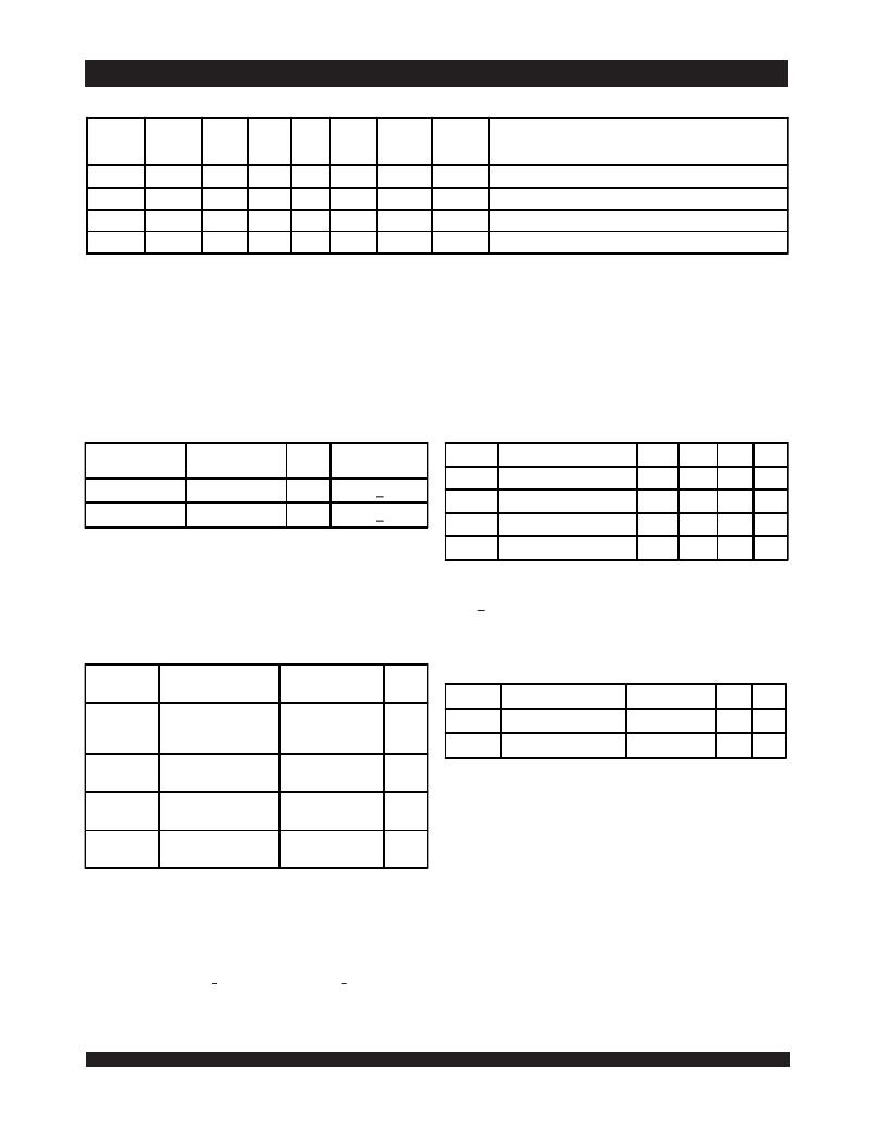
Truth Table II—Address Counter Control (1,2)
Industrial and Commercial Temperature Ranges
Previous
Internal
L
L
External
Address
An
X
X
X
Internal
Address
X
An
An + 1
X
Address
Used
An
An + 1
An + 1
A 0
CLK
↑
↑
↑
↑
ADS
L (4)
H
H
X
CNTEN
X
(5)
H
X
CNTRST
H
H
H
(4)
I/O (3)
D I/O (n)
D I/O (n+1)
D I/O (n+1)
D I/O (0)
MODE
External Address Used
Counter Enabled—Internal Address generation
External Address Blocked —Counter disab led (An + 1 reused)
Counter Reset to Address 0
NOTES:
1. "H" = V IH, "L" = V IL, "X" = Don't Care.
2. CE 0 , LB , UB , and OE = V IL ; CE 1 and R/ W = V IH .
3. Outputs configured in Flow-Through Output mode: if outputs are in Pipelined mode the data out will be delayed by one cycle.
4. ADS and CNTRST are independent of all other signals including CE 0 , CE 1 , UB and LB .
5. The address counter advances if CNTEN = V IL on the rising edge of CLK, regardless of all other signals including CE 0 , CE 1 , UB and LB .
.
Recommended Operating Recommended DC Operating
Temperature and Supply Voltage (1) Conditions
5633 tbl 03
Grade
Ambient
Temperature (1)
GND
Vcc
Symbol
Parameter
Min.
Typ.
Max.
Unit
V CC
Supply Voltage
4.5
5.0
5.5
V
Commercial
Industrial
0 O C to +70 O C
-40 O C to +85 O C
0V
0V
5.0V + 10%
5.0V + 10%
GND
V IH
Ground
Input High Voltage
0
2.2
0
____
0
6.0 (1)
V
V
5633 tbl 04
NOTES:
V IL
Input Low Voltage
-0.5 (2)
____
0.8
V
1. Industrial temperature: for specific speeds, packages and powers contact your
sales office.
2. This is the parameter T A . This is the "instant on" case temperature.
NOTES:
1. V TERM must not exceed V cc + 10%.
2. V IL > -1.5V for pulse width less than 10ns.
5633 tbl 05
Absolute Maximum Ratings (1)
Symbol Rating Commercial
Unit
Capacitance (1)
(T A = +25°C, f = 1.0MH z )
& Industrial
Symbol
Parameter
Conditions (2)
Max.
Unit
V TERM
(2)
Terminal Voltage
with Respect
-0.5 to +7.0
V
C IN
Input Capacitance
V IN = 3dV
9
pF
C OUT
to GND
(3)
Output Capacitance
V OUT = 3dV
10
pF
T BIAS
T STG
Temperature
Under Bias
Storage
Temperature
-55 to +125
-65 to +150
o
o
C
C
5633 tbl 07
NOTES:
1. These parameters are determined by device characterization, but are not
production tested.
2. 3dV references the interpolated capacitance when the input and output switch from
0V to 3V or from 3V to 0V.
I OUT
DC Output
50
mA
3. C OUT also references C I/O .
Current
NOTES:
5633 tbl 06
1. Stresses greater than those listed under ABSOLUTE MAXIMUM RATINGS may
cause permanent damage to the device. This is a stress rating only and functional
operation of the device at these or any other conditions above those indicated in the
operational sections of this specification is not implied. Exposure to absolute
maximum rating conditions for extended periods may affect reliability.
2. V TERM must not exceed V cc + 10% for more than 25% of the cycle time or 10ns
maximum, and is limited to < 20mA for the period of V TERM > V cc + 10%.
5
6.42
发布紧急采购,3分钟左右您将得到回复。
相关PDF资料
IDT709379L7PFG
IC SRAM 576KBIT 7NS 100TQFP
IDT70P257L55BYGI
IC SRAM 128KBIT 55NS 100BGA
IDT70P258L55BYI
IC SRAM 128KBIT 55NS 100BGA
IDT70T3339S200BCG
IC SRAM 9MBIT 200MHZ 256BGA
IDT70T3509MS133BP
IC SRAM 36MBIT 133MHZ 256BGA
IDT70T3519S133DRI
IC SRAM 9MBIT 133MHZ 208QFP
IDT70T3539MS166BCG
IC SRAM 18MBIT 166MHZ 256BGA
IDT70T3719MS166BBG
IC SRAM 18MBIT 166MHZ 324BGA
相关代理商/技术参数
IDT709359L7PF
功能描述:IC SRAM 144KBIT 7NS 100TQFP RoHS:否 类别:集成电路 (IC) >> 存储器 系列:- 标准包装:45 系列:- 格式 - 存储器:RAM 存储器类型:SRAM - 双端口,异步 存储容量:128K(8K x 16) 速度:15ns 接口:并联 电源电压:3 V ~ 3.6 V 工作温度:0°C ~ 70°C 封装/外壳:100-LQFP 供应商设备封装:100-TQFP(14x14) 包装:托盘 其它名称:70V25S15PF
IDT709359L7PF8
功能描述:IC SRAM 144KBIT 7NS 100TQFP RoHS:否 类别:集成电路 (IC) >> 存储器 系列:- 标准包装:45 系列:- 格式 - 存储器:RAM 存储器类型:SRAM - 双端口,异步 存储容量:128K(8K x 16) 速度:15ns 接口:并联 电源电压:3 V ~ 3.6 V 工作温度:0°C ~ 70°C 封装/外壳:100-LQFP 供应商设备封装:100-TQFP(14x14) 包装:托盘 其它名称:70V25S15PF
IDT709359L7PFI
功能描述:IC SRAM 144KBIT 7NS 100TQFP RoHS:否 类别:集成电路 (IC) >> 存储器 系列:- 标准包装:1,000 系列:- 格式 - 存储器:RAM 存储器类型:SRAM - 双端口,同步 存储容量:1.125M(32K x 36) 速度:5ns 接口:并联 电源电压:3.15 V ~ 3.45 V 工作温度:-40°C ~ 85°C 封装/外壳:256-LBGA 供应商设备封装:256-CABGA(17x17) 包装:带卷 (TR) 其它名称:70V3579S5BCI8
IDT709359L7PFI8
功能描述:IC SRAM 144KBIT 7NS 100TQFP RoHS:否 类别:集成电路 (IC) >> 存储器 系列:- 标准包装:45 系列:- 格式 - 存储器:RAM 存储器类型:SRAM - 双端口,异步 存储容量:128K(8K x 16) 速度:15ns 接口:并联 电源电压:3 V ~ 3.6 V 工作温度:0°C ~ 70°C 封装/外壳:100-LQFP 供应商设备封装:100-TQFP(14x14) 包装:托盘 其它名称:70V25S15PF
IDT709359L9BF
功能描述:IC SRAM 144KBIT 9NS 100FBGA RoHS:否 类别:集成电路 (IC) >> 存储器 系列:- 标准包装:45 系列:- 格式 - 存储器:RAM 存储器类型:SRAM - 双端口,异步 存储容量:128K(8K x 16) 速度:15ns 接口:并联 电源电压:3 V ~ 3.6 V 工作温度:0°C ~ 70°C 封装/外壳:100-LQFP 供应商设备封装:100-TQFP(14x14) 包装:托盘 其它名称:70V25S15PF
IDT709359L9PF
功能描述:IC SRAM 144KBIT 9NS 100TQFP RoHS:否 类别:集成电路 (IC) >> 存储器 系列:- 标准包装:45 系列:- 格式 - 存储器:RAM 存储器类型:SRAM - 双端口,异步 存储容量:128K(8K x 16) 速度:15ns 接口:并联 电源电压:3 V ~ 3.6 V 工作温度:0°C ~ 70°C 封装/外壳:100-LQFP 供应商设备封装:100-TQFP(14x14) 包装:托盘 其它名称:70V25S15PF
IDT709359L9PF8
功能描述:IC SRAM 144KBIT 9NS 100TQFP RoHS:否 类别:集成电路 (IC) >> 存储器 系列:- 标准包装:72 系列:- 格式 - 存储器:RAM 存储器类型:SRAM - 同步 存储容量:9M(256K x 36) 速度:75ns 接口:并联 电源电压:3.135 V ~ 3.465 V 工作温度:-40°C ~ 85°C 封装/外壳:100-LQFP 供应商设备封装:100-TQFP(14x14) 包装:托盘 其它名称:71V67703S75PFGI
IDT709369L12PF
功能描述:IC SRAM 288KBIT 12NS 100TQFP RoHS:否 类别:集成电路 (IC) >> 存储器 系列:- 标准包装:1,000 系列:- 格式 - 存储器:RAM 存储器类型:SRAM - 双端口,同步 存储容量:1.125M(32K x 36) 速度:5ns 接口:并联 电源电压:3.15 V ~ 3.45 V 工作温度:-40°C ~ 85°C 封装/外壳:256-LBGA 供应商设备封装:256-CABGA(17x17) 包装:带卷 (TR) 其它名称:70V3579S5BCI8
